Looking for a propellent force
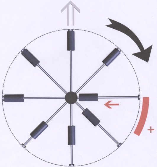
The below picture shows an imaginary athlete able to twirl 8 hammers.
There is a virtual ring around him, graduated in hours, with a clockwise rotation of the hammers. The left shoulder of our athlete corresponds to 9 oclock and his right shoulder to 15; in front of him: from 9 to 15 (10,11, 12, 13,14), and behind him: from 15 to 9. The athlete twirls his hammers in such a way that, between 15and 17, each hammer is drawn back to his head, then released from 17 onwards (we will come back to this point later). Each mass is released at 17 and back in its place, at the end of the rope, at 21; therefore, in this sector, the hammers are quite independent of the driving central axle, figured by our athlete. At the same time the athlete has to stand a traction effect, as a result of the permanent traction of hammers in the sector 9 to 15. The lack of traction in the lower hemicycle and the traction effect in the upper one generates a propellent force. Now, lets go back to the 15-17 sector. It is obvious that the athlete, in order to draw back the hammer to his head, has to make an effort; the corresponding force reduces the overall traction (3rd Newtons law) ( it must be mentioned that the drawing has been overdone on purpose on the picture, for comprehensibility reasons). Technique enables us to decrease it and consequently its effect on the whole system. I emphasise in advance that, from the athletes image to the device submitted to your consideration, the image will remain the reference for sectors, numbers of rods for sliding masses as well as principles. 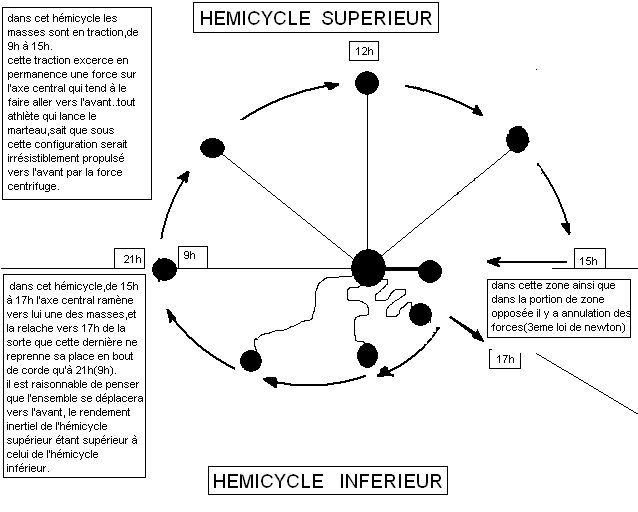 The latest sketch shows the integration into a hull of the power unit set out in the above drawings - and that is itself only one of many possible versions of applying the process.
Actually, various shapes and techniques can put the principles of this process into practice. In this particular case, all techniques mentioned in the above texts and drawings are used. The streamlined tailplane shown by the drawing has only a symbolic meaning, because it is quite possible, from a technological standpoint, to use only the process for making in a 3 - dimensional space. For instance, we can think of fitting the power unit on a ball-and-socket joint, which allows to steer it in the 3 - dimensional space. We can also think of thrust inversions by fitting the electromagnet on a circular rotating pad. The power unit can be fed with various kinds of energy existing nowadays; its consumption is lesser in comparison with the consumption of currently used spacecrafts. With such a flying machine the deep space exploration becomes feasible, thanks to the speed that can be reached without an excessive consumption. Fed by a nuclear pile, with a 1 G acceleration, which is currently workable, the flying machine could reach a 964 Km/sec. speed. It is obvious that more important thrusts could be used in the case of uninhabited space probes. Within the context of our research, and in order to be in a position to carry on with them, we are looking for partners or sponsors. Our team is able to finalise an inhabited vehicle; the tests, after financing, could take place within the 2 years following the starting date of the work. We are convinced that the device set out is of the utmost relevance to the space propulsion to come and any involvement in this move would provide any potential investor with positive results. Conclusion
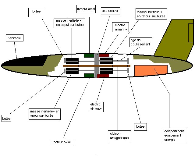 Cockpit
Amagnetic
partition Inertial mass + leaning on stop
Electro- magnet+
Axial motor
Stop
Inertial mass + leaning on stop
Stop
Energy equipment compartment
Rod for sliding masses
Electro- magnet +
Inertial mass + going back to stop
Central axle
Axial engine
stop
Plane view of an half device
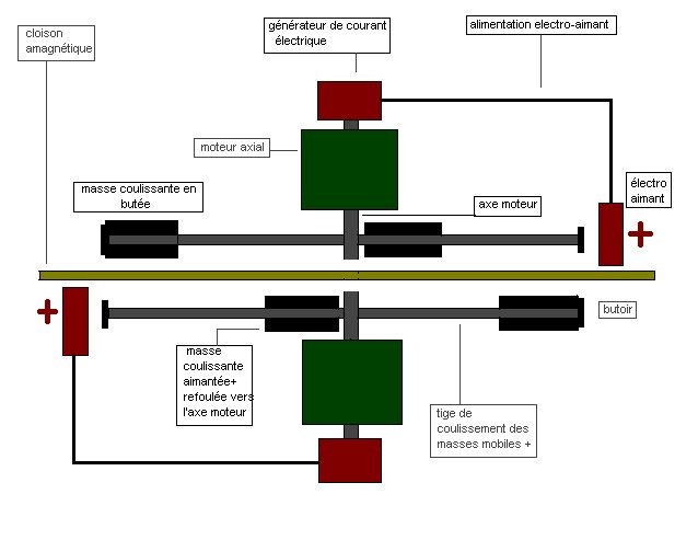
Representation of an half-device, without motor or generator.
It can be straight connected to the above drawings, with regard to the application of the force underscored in the process. In order to avoid any possible misunderstanding, it may be useful to remind that the electromagnet is only used for sending the sliding positive masses back to the central axle, then releasing them. In no way this electromagnet is involved in the rotation of the system; it is fixed and the rotation of the moving masses is operated by an axial engine (driving central axle). As it is in the previous drawings, there is a great traction generated by the masses on their stops, transmitted to the whole upper hemicycle; in the lower hemicycle the masses do not lean on any support and can be regarded, during their way back to the stops, as independent and without effect on the overall system UPPER HEMICYLE
LOWER HEMICYCLE
In this sector, as well as in the stretch of the opposite sector, forces cancel each other out (3rd Newton law)
In this hemicycle the masses are under tension from 9 to 15.
Such a tension exerts a
traction effect on the central axle, pulling it forward.
Any athlete, who throws hammer, knows that, under this kind of configuration , he would be irresistibly pulled forward, by the centrifugal force. 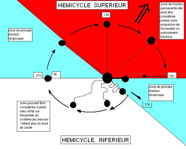 Reciprocal
action area UPPER HEMICYCLE
  LOWER HEMICYCLE
UPPER HEMICYCLE
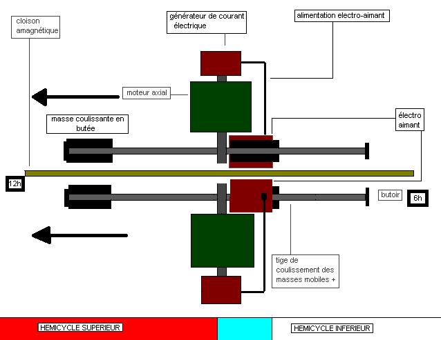
Rod for
sliding masses + Stop
Electro- magnet
Sliding mass on stop
Axial engine
Electromagnet feeding
Generator
Rod for sliding masses +
Sliding mass on stop
Sliding magnetic mass + pushed back to driving axle
Stop
Driving axle
Electromagnet
feeding
Generator
Electro-
magnet Axial engine
Amagnetic partition
This representation is complementary with the previous drawing.
Here appear the generators, and the motors, overdone on purpose, for comprehensibility reasons. We have to point out that, since the beginning, the process is based on 8 rods for sliding masses; there is nothing preventing from fitting more than that. In this connection, it is quite possible to pile devices so as to increase the thrust. The present configuration is not the only one studied by our team; simplified versions are already under consideration and development; they will not be taken up here Schematic representation of a full contrarotation device
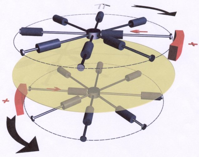 This drawing is based on the same principles as previous sketches and texts.
The contrarotation aims at balancing the forces, so as to ensure a rectilinear thrust to the overall system. In this drawing, the engine operating the rotation is left aside, as well as the generators feeding the electromagnets. An amagnetic partition is shown, aiming at minimising the influence of one system on the other. Like in the previous drawings the forces are uncoupled (lower hemicycle - upper hemicycle) with a positive result for the upper hemicycle where the masses are continuously pulling on rods and stops. Contrarotation device
 Reciprocal action area
LOWER HEMICYCLE
Reciprocal action area
Permanent traction area, considered to be propellent ( or more exactly : tractive)
Placez ici le contenu de id "cache"
Area without any effect on the overall system, masses being not at the end of the rope
|
| THE WHOLE SYSTEM IS COVERED BY A PATENT ISSUED BY THE INPI... |
| For any further information : bernardbastita@yahoo.fr bernard.bastita@laposte.net |
Good day !
From March, 28 till March, 31st, 2006 in Moscow in territory CEC "Sokolniki" will pass
IX Moscow International Salon of the industrial property "Archimedes". The Salon is supported
by the Government of Moscow, the World organization of intellectual property, Administration of
the President of the Russian Federation, Ministry of economy and development, Commercial and
industrial chamber of the Russian Federation, the Moscow commercial and industrial chamber,
the Ministry of Defense of Russia, Federal service on intellectual property, patents and
trade marks, the Russian academy of sciences, and Association "SOUZPATENT".
Best wishes
Anastasia
Best wishes
Anastasia